Monday, October 28, 2013

Function symbols and their uses:


Shape like circles, squares, diamonds, hexagons, and lines used to represent the hardware and software instruments and functions as follows:


  • Discrete Devices and Functions, represents discrete hardware instruments and functions that are implemented in non-microprocessor-based systems similar to single-case transmitters, controllers, indicators etc.
  • Shared Devices and Functions, represents shared and distributed software analog instruments and functions that are implemented in microprocessor-based systems similar to distributed control or programmable logic control systems.


  • Shared On–Off Devices and Functions, represents shared and distributed on–off software instruments and functions that are implemented in microprocessor-based control systems similar or equal to a distributed control or programmable logic control systems.


  • Computer Devices and Functions, represents shared and distributed on–off software instruments and functions that are implemented in a computer-based control system


Friday, October 18, 2013

Line designation or line numbering


Line numbering or designation for each major line, especially header is very important to trace flow continuation for a multipage project drawing. There is several standard for such numbering system.

A line can be identified by its number, fluid to be handled, location in plant, line size, MOC etc. These parameters are the basic elements of line identity. The schematic representation of the parameters is as shown below:
line numbering

Detail Description:

Line Number: Line number is a unique number assigned to every line. Every line must have a different line number i.e. the number should not be repeated for various lines.

Depending on the type of fluid the lines can be further numbered. For example lines for process fluids can have numbering in one range, say, 1 to 100, utility lines can have numbering falling in another range, say, 101 to 200 and so on.


Fluid to be carried: Process lines are meant for handling various fluids. The fluids handled can be classified as Process fluids (which further includes the raw materials, the intermediate streams and the final product ) Utilities (which includes cooling water, chilled water, steam, thermic fluids, soft water, DM water etc.). For nomenclature, each of these lines are given specific codes depending on the fluid handled
CWS may indicate cooling water supply, CWR may indicate cooling water return, DMS may indicate DM water supply and so on.


Location or Area: This parameter is included in the nomenclature so as to indicate the origin of any stream in various locations of the plant. The various sections of plants are Raw material storage, processing, Intermediate Product Storage, Final product storage, Water treatment section, utility section, waste treatment section etc.


Material of Construction: Commercial pipes are available with various materials of constructions. Most commonly used materials are CS, AISI 304, AISI 316, Copper, PVC etc.
In the nomenclature MOC can be written as it is like CS for Carbon steel, AISI 304, AISI316 etc. for various grades of Stainless Steel.
Second way can be giving code for various MOC. For example Code 1 can denote CS, Code 2 can denote AISI 304 and so on.


Line size: Although the selection of line is a job of piping engineer, the line sizing can be done by Process or Piping engineer. Commercial pipes are available either as NB (Nominal Bore ) based or OD (Outside Diameter) based depending on the material of construction.
The standard sizes on NB basis are 25, 50, 80,100,150,200 etc. The corresponding sizes on OD basis are 33.4, 60.3, 88.9, 114.3, 168.3, 219.1 etc. The same are mentioned in the nomenclature.


Phase: Materials that are handled in Process plants exist in different phases. In general the flow can classified as single phase flow, two phase flow and three phase flow. Single phase flow indicates flow of solid, liquid, gases or vapors. Two phase flow indicates combination of any two of these
solid + liquid, solid + gases, liquid + vapors etc.
Three phase flow indicated combination of any three of these.
The inclusion of this parameter in the nomenclature may be optional, but the inclusion proves to be very helpful especially when the process involves several phase flows through various lines in the plant.
The details of phase can be given by complete name of the phase like solid, liquid etc.
Letters such as S, L, G and V can be used to denote respectively solids, liquids, gas and vapors.


Insulation: Process equipment and pipes are insulated either to prevent heat loss to the surroundings or to prevent heat gain from the surroundings. Accordingly there are two types of insulations – hot and cold. Depending on the temperature inside the pipe and that of the surroundings, the nature of insulation differs.
The terms “H” and “C” can thus be used to indicate the type of insulation. The inclusion of this parameter in the nomenclature is essential because it indicates the nature of fluid in the pipe which is mainly required for personnel safety in the plant.


Other: At times it becomes necessary to provide additional details in the nomenclature. These include jacketing of pipe, pipe tracing, welding type, and special lines like IBR etc. The additional detail can be indicated as it is in the nomenclature.e


A typical line number / designation should be as follows:


6044-25-L-SW4-40S-IH

6044: Serial No/Sequence

25: Nominal diameter of the line

L: Service Code

SW4: Welding Type

40S: Material Spec

IH: Insulation Type

For numbering purpose many organizations have their own format of numbering which is prepared using standard rules for equipment and line numbering.

Every organization has their own master sheet or drawing which is prepared for the purpose of standard reference and it must include all the standard symbol, notation and format required for future drawing.


Introduction to P&ID
 

Thursday, October 17, 2013

More about PFD (Process Flow Diagram)


Process Flow Diagram (PFD) is a simple form of diagram that uses symbols to identify instruments and vessels and to describe the primary flow path through a process. It illustrates the general process streams, major equipment and key control loops. They also provide detailed mass energy balance data along with major stream composition and physical properties


The process flow diagram (PFD) represents a quantum step up from the BFD in terms of the amount of information that it contains. The PFD contains the bulk of the chemical engineering data necessary for the design of a chemical process. For all of the diagrams discussed in this chapter, there are no universally accepted standards. The PFD from one company will probably contain slightly different information than the PFD for the same process from another company. Having made this point, it is fair to say that most PFDs convey very similar information.

It is clear that the PFD is a complex diagram requiring a substantial effort to prepare. It is essential that it should remain uncluttered and be easy to follow, to avoid errors in presentation and interpretation. Often PFDs are drawn on large sheets of paper, and several connected sheets may be required for a complex process. Because of the page size limitations associated with this text, complete PFDs cannot be presented here. Consequently, certain liberties have been taken in the presentation of the PFDs in this text. Specifically, certain information will be presented in accompanying tables, and only the essential process information will be included on the PFD. The resulting PFDs will retain clarity of presentation, but the reader must refer to the flow summary and equipment summary tables in order to extract all the required information about the process.


Nowadays with the advent of computers and new technology, we tend to use computerized process flow diagrams. In old computer era, we used to draw process flow diagrams with the help of supporting software manually but now we have many process simulators that automatically create process flow diagrams. We can also make use of the Computer Aided Design (CAD) technology or flow chart software to enhance our process flow diagram skills


Information Provided in a Flow Summary:


  • Stream Number


  • Temperature (°C)


  • Pressure (bar)


  • Vapor Fraction


  • Total Mass Flow rate (kg/h)


  • Total Mole Flow rate (kmol/h)


  • Individual Component Flow rates (kmol/h)


  • Optional Information>


  • Component Mole Fractions


  • Component Mass Fractions


  • Individual Component Flow rates (kg/h)


  • Volumetric Flow rates (m3/h)


  • Significant Physical Properties


  • Density


  • Viscosity>


  • Thermodynamic Data


  • Heat Capacity


  • Stream Enthalpy


  • Stream Name


  • More about P&ID


    PFDs should PFDs should not
    • Process Piping - major process lines
    • Major equipment symbols, names and identification numbers
    • Flow directions
    • Major bypass and recirculation lines
    • Control valves and valves that affect operation of the system
    • Control loops that affect operation of
    • Pipe classes or piping line numbers
    • Process control instrumentation (sensors and final elements)
    • Minor bypass lines
    • Isolation and shutoff valves
    • Maintenance vents and drains
    • Relief and safety valves
    • Flanges


    Friday, March 8, 2013

    Introduction to P&ID


    Click here for Piping and Instrumentation Diagram main article

    The flow sheet or flow diagram are often used in context of engineering and design application. Although this terminology is not most accurate to describe P&IDs, it’s sufficient to describe the overall family of a process based diagram to which P&IDs belong.


    We can divide the process diagram in three type or step:

    BFD : The Block Flow Diagram
    PFD : The Process Flow Diagram
    P&ID : The Process and Instrumentation Diagram

    BLOCK FLOW DIAGRAM


    The beauty of a BFD is its ability to outline the complete process on little more than a single sheet. The diagram usually resemble an organized chart, containing mainly text enclosed by boxes, interconnecting lines, the process commodities they transport and flow arrows to indicate flow directions.


    INFORMATION PROVIDED BY A BFD


    A good BFD typically contains the following:
    • Individual pieces of equipment or equipment package that are denoted by a single symbol, typically a rectangle.
    • Clear label illustrating function
    • Lines linking equipment or process to show flow direction.
    • The order of process flow arranged and if possible with a gravity bias.
    • Whenever more than one line leaves a process then the processed commodity in each line should be clearly marked


    TYPICAL BFD

    BFD

    PROCESS FLOW DIAGRAM

    Process flow diagram carry more information than the block flow diagram. They show more detail about major equipment & sub system and the flow. PFD include information of the pressure and temperature of the feed and product line to and from all major equipment. Also indicate the main header and points of all control. It’s consider as the precursor of P&IDs

    Information provided by a PFD

    A typical PFD shows the following items:
    • Process piping
    • Process flow direction
    • Major bypass and recirculation lines.
    • Major equipment represented by simplified symbols.
    • Control and process critical valves
    • System ratings and operational values.
    • Composition of fluids
    • Connection between systems.

    TYPICAL PFD

    PFD

    PROCESS AND INSTRUMENTATION DIAGRAM


    The Piping and Instrumentation Diagram (P&ID), based on the Process Flow Diagram (PFD), represents the technical realization of a process by means of graphical symbols for equipment and piping together with graphical symbols for process measurement and control functions.

    A P&ID carries a wealth of information that span engineering disciplines to define a process. The representation and designation of all the equipment, instrumentation and piping should comply with the requirements of Standard. Auxiliary systems may be represented by rectangular boxes with reference to the separate diagrams

    For processing facilities, it is a pictorial representation of:

    Ø Key piping and instrument details

    Ø Control and shutdown schemes

    Ø Safety and regulatory requirements and

    Ø Basic start up and operational information

    INFORMATION PROVIDED BY P&ID:

    • Permanent start-up and flush lines.
    • Flow directions and Interconnections references.
    • Control inputs and outputs, interlocks and Computer control system input.
    • Interfaces for class changes.
    • Identification of components and subsystems delivered by others.
    • Instrumentation and designations.
    • Mechanical equipment with names and numbers.
    • All valves and their identifications.
    • Process piping, sizes and identification
    • Miscellaneous - vents, drains, special fittings, sampling lines,reducers, increasers and swagers.
    TYPICAL P&ID

    P&ID

    Thursday, March 7, 2013

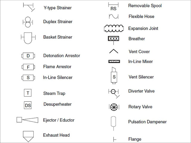
    PIPING DAIGRAM SYMBOL


    Symbol is the basic notation to describe or represent a P&ID. To read and interpret piping and instrument drawing , the reader must learn the meaning of the symbol. We will discuss about the common symbols that are used to depict fluid process plant.

    In general all the symbols used in P&ID are as per ISA or ANSI standard. But any organization may have their own standard which is derived from international standard.

    line symbol
    LINE SYMBOL


    p&id compressor
    COMPRESSOR SYMBOL

    instrument function
    FUNCTION SYMBOLS


    more function

    FUNCTION SYMBOLS


    pump symbol
    PUMP SYMBOLS


    storage symbol
    STORAGE SYMBOL


    mechanical fittings
    FITTINGS SYMBOL


    heat exchanger
    EXCHANGER SYMBOL

    Wednesday, March 6, 2013

    Piping Symbols used in P&ID


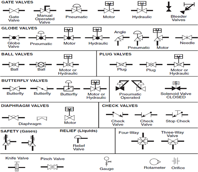
    Symbols for several types of valve generally used in process plant:


    Valve symbol
    ____________________________________________________________________


    Notation used to describe a valve's position(Open/Closed/Partially open etc):

    valve position
    ____________________________________________________________________


    Symbol and abbreviation used for identifying types of instruments and their function:

    instrument function abbreviation
    ____________________________________________________________________

    Miscellaneous symbol used to mention direction and continuity:


    miscellaneous symbol

    Tuesday, March 5, 2013

    P&ID ABBREVIATION AND IDENTIFICATION


    Abbreviation is used to define:
    1. An equipment to specify its type or service.
      • Example: For a Pump generally ’AP’ abbreviation is used for numbering. AP1002, AP6009 etc.
      • Example: For a Vacuum Pump generally ’AV’ abbreviation is used for numbering. AV1012, AP4007 etc.
      • Example: For a storage tank 'ST' and for vessel 'AB' is used for numbering.
    2. A pipe line to specify its service.
      • Example: ‘CWR’ is used for the Cooling Water Supply line.
      • Example: ‘HOS’ used for Hot Oil Supply line.
    3. An Instrument to define its function.
      • Example: ‘PRV’ used for control valve to Control Pressure.
      • Example: ‘FIC’ used for Instrument which is used to Indicate and Control Flow.

    Bellow is list of some abbreviation generally used in a standard P&ID:


    DRAIN/SEWER ABBREVIATION


    MISCELLANEOUS ABBREVIATION


    ABBREVIATION FOR UTILITY SERVICE


    ABBREVIATION FOR UTILITY SERVICE


    INSTRUMENT ABBREVIATION

    Saturday, March 2, 2013

    Know P&ID


    More about P&ID

    A P&ID sheet can be divided in following parts:
    • Title Block (1st block, 2nd block, 3rd block & other information as scale, soft copy reference etc.)

    • Grid System

    • Revision Block

    • Notes and Legend

    • Equipment Specification

    • Drawing (Graphic Portion)

    TITLE BLOCK:

    Generally title block consist 3 Area: 1st area contains drawing title, number, location or area, site and vendor. 2nd area contains signature, information of drafting, verification, approval and control. 3rd area is reference area which contains reference block and drawing information.

    DIFFERENT AREA OF A TITLE BLOCK SHOWN BELLOW:


    BELLOW IS AN EXAMPLE OF A TYPICAL TITLE BLOCK:


    GRID SYSTEM:


    Because of drawing tend to be large & complex it quite difficult to find a specific point in a sheet. This is especially true when a wire or pipe is continued on a second drawing. To locate the point in reference print most drawing has 2D coordinate grid system. The grid consist letter, number or both that run horizontally and vertically around the drawing.

    TYPICAL GRID USED IN P&ID:


    REVISION BLOCK:

    If any change is done in a system or equipment or specification in drawings the drawing must be redrafted and reissued with a new version of the original drawing.The revision details must be mentioned in Revision Block. The original drawing must be of version 0.


    NOTES AND LEGEND:

    Because of the importance of understanding all the symbol & convention used in a drawing the notes and legend section must be review before reading a drawing.The legend and note section of a drawing list & explain any special symbol & convention used on the drawing. Any notes required for understanding a drawing can be mentioned here.


    EQUIPMENT SPECIFICATION:

    In this section the specification of essential equipment can be mentioned.
    • A vessel/ tank can be specified with capacity, MOC, Empty weight, jacketing detail, tubing detail etc.

    • A pump can specified with it’s disch. capacity, head, RPM, drive type etc.

    • A motor can be specified with it’s RPM, rating current, voltage, frequency etc.

    DRAWING:

    Drawing area is the graphics section where the pictorial view of system/project/equipment is described graphically using standard symbol & procedure.

    EXAMPLE OF A STANDARD DRAWING SHEET:


    Generally any organization customizes and makes their own standard focusing on ISA standard.


    Pages - Menu