Tuesday, November 5, 2013

Understanding Control loop in P&ID


About Control Loop:

Modern production systems use automatic control systems where control is carried out with minimal or without human intervention. The ‘Control loops’ used in a process industry in terms of a combination of two or more instruments or control functions arranged so that signals pass from one to another for the purpose of measurement and/or control of a process variable. The goal of process control instrumentation is to measure, monitor, and or control a process.


Following three tasks is associated with a control loop.
  • Measurement
  • Comparison
  • Adjustment
Before we proceed it’s very essential to have a basic concept on the following terms which are needed to understand a control loop in P&ID:
  1. Instrument and controller symbol and identification letter.
  2. Different type of function symbols and their uses.
  3. Symbol of different type of line and device  associated with control loop.
  4. Instrument numbering.

To read out a control loop fro a P&ID first we have to identify the following things:
  • Variable/variables are to be controlled by the control loop.
  • Variables need to measure for functioning the control scheme.
  • Type of instrument used for measuring variable.
  • Type of controller, device and function used for controlling purpose.
  • Type of signal and connection used for interlinking and transmission purpose.

EXAMPLE:

process control loop

In the above example the tank is filling with the pipe line above the tank and emptying through the bottom pipe line.  The level of the liquid in the tank need to control for process purpose. So the control loop is designed here just to control the tank level. The level or height of the liquid is the process variable here and the level transmitter (LT) is used to measure the process variable continuously.A level controller (LC) is used as controller and a level control valve (LV) is used to control the flow inside the bottom pipe line.

Here the control loop is working in following steps:
  • First the level transmitter (LT) is measuring the level.
  • The measuring value is transmitted to level controller (LC) through electrical signal.
  • The controller decide what to do depending on set or desired value.
  • Then the controller send required command to the level control valve (LV) through a pneumatic signal.
  • Finally the control valve increase or decrease the flow as per controller signal.

Instrument Tag or Number


An Instrument number or tag has two parts which is combination of letter and number.
  • Identification letter for indicating the function and purpose of use.
  • An individual tag number/Loop No./serial number.

Instrument tag

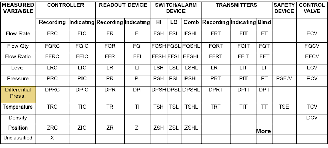
Letter is used to classify the instrument by it's function and number is used to identify the loop/interlock. Identification letters on the ISA symbols indicate:
  • The variable being measured (e.g. flow, pressure, temperature).
  • The device’s function (e.g., transmitter, switch, valve, sensor, indicator).
  • Some modifiers (e.g., high, low, multifunction).
In the instrument tag number in above figure the initial letter indicates the measured variable. The second letter indicates a modifier, readout, or device function. The third letter usually indicates either a device function or a modifier.

In that cases where the instrument is considered to be identified by it's location/area then the instrument tag number format will be as bellow:


Connected line/link and device symbol used in control loop:


Different types of symbol are used to describe the connection/link between instrument, device, controller etc.

Following line symbol are generally used for representing a complete control loop:

Symbol of control and measuring device used in process control:

Valve and Actuator


Measuring device


Instrument symbol and Identification


Measuring Instrument Symbol:


Final Element Symbol:


Related Device Symbol:


Instrument Identification Letter:


Monday, October 28, 2013

Function symbols and their uses:


Shape like circles, squares, diamonds, hexagons, and lines used to represent the hardware and software instruments and functions as follows:


  • Discrete Devices and Functions, represents discrete hardware instruments and functions that are implemented in non-microprocessor-based systems similar to single-case transmitters, controllers, indicators etc.
  • Shared Devices and Functions, represents shared and distributed software analog instruments and functions that are implemented in microprocessor-based systems similar to distributed control or programmable logic control systems.


  • Shared On–Off Devices and Functions, represents shared and distributed on–off software instruments and functions that are implemented in microprocessor-based control systems similar or equal to a distributed control or programmable logic control systems.


  • Computer Devices and Functions, represents shared and distributed on–off software instruments and functions that are implemented in a computer-based control system


Friday, October 18, 2013

Line designation or line numbering


Line numbering or designation for each major line, especially header is very important to trace flow continuation for a multipage project drawing. There is several standard for such numbering system.

A line can be identified by its number, fluid to be handled, location in plant, line size, MOC etc. These parameters are the basic elements of line identity. The schematic representation of the parameters is as shown below:
line numbering

Detail Description:

Line Number: Line number is a unique number assigned to every line. Every line must have a different line number i.e. the number should not be repeated for various lines.

Depending on the type of fluid the lines can be further numbered. For example lines for process fluids can have numbering in one range, say, 1 to 100, utility lines can have numbering falling in another range, say, 101 to 200 and so on.


Fluid to be carried: Process lines are meant for handling various fluids. The fluids handled can be classified as Process fluids (which further includes the raw materials, the intermediate streams and the final product ) Utilities (which includes cooling water, chilled water, steam, thermic fluids, soft water, DM water etc.). For nomenclature, each of these lines are given specific codes depending on the fluid handled
CWS may indicate cooling water supply, CWR may indicate cooling water return, DMS may indicate DM water supply and so on.


Location or Area: This parameter is included in the nomenclature so as to indicate the origin of any stream in various locations of the plant. The various sections of plants are Raw material storage, processing, Intermediate Product Storage, Final product storage, Water treatment section, utility section, waste treatment section etc.


Material of Construction: Commercial pipes are available with various materials of constructions. Most commonly used materials are CS, AISI 304, AISI 316, Copper, PVC etc.
In the nomenclature MOC can be written as it is like CS for Carbon steel, AISI 304, AISI316 etc. for various grades of Stainless Steel.
Second way can be giving code for various MOC. For example Code 1 can denote CS, Code 2 can denote AISI 304 and so on.


Line size: Although the selection of line is a job of piping engineer, the line sizing can be done by Process or Piping engineer. Commercial pipes are available either as NB (Nominal Bore ) based or OD (Outside Diameter) based depending on the material of construction.
The standard sizes on NB basis are 25, 50, 80,100,150,200 etc. The corresponding sizes on OD basis are 33.4, 60.3, 88.9, 114.3, 168.3, 219.1 etc. The same are mentioned in the nomenclature.


Phase: Materials that are handled in Process plants exist in different phases. In general the flow can classified as single phase flow, two phase flow and three phase flow. Single phase flow indicates flow of solid, liquid, gases or vapors. Two phase flow indicates combination of any two of these
solid + liquid, solid + gases, liquid + vapors etc.
Three phase flow indicated combination of any three of these.
The inclusion of this parameter in the nomenclature may be optional, but the inclusion proves to be very helpful especially when the process involves several phase flows through various lines in the plant.
The details of phase can be given by complete name of the phase like solid, liquid etc.
Letters such as S, L, G and V can be used to denote respectively solids, liquids, gas and vapors.


Insulation: Process equipment and pipes are insulated either to prevent heat loss to the surroundings or to prevent heat gain from the surroundings. Accordingly there are two types of insulations – hot and cold. Depending on the temperature inside the pipe and that of the surroundings, the nature of insulation differs.
The terms “H” and “C” can thus be used to indicate the type of insulation. The inclusion of this parameter in the nomenclature is essential because it indicates the nature of fluid in the pipe which is mainly required for personnel safety in the plant.


Other: At times it becomes necessary to provide additional details in the nomenclature. These include jacketing of pipe, pipe tracing, welding type, and special lines like IBR etc. The additional detail can be indicated as it is in the nomenclature.e


A typical line number / designation should be as follows:


6044-25-L-SW4-40S-IH

6044: Serial No/Sequence

25: Nominal diameter of the line

L: Service Code

SW4: Welding Type

40S: Material Spec

IH: Insulation Type

For numbering purpose many organizations have their own format of numbering which is prepared using standard rules for equipment and line numbering.

Every organization has their own master sheet or drawing which is prepared for the purpose of standard reference and it must include all the standard symbol, notation and format required for future drawing.


Introduction to P&ID
 

Pages - Menu