Tuesday, December 3, 2013

UTILITY FLOW DIAGRAMS and P&ID


The Utility Flow Diagram shall be prepared as separate drawing titledas "Utilities Flow Diagram". The distribution of utilities for plant operation shall be shown on the drawing. The utilities for plant operation are generally classified as follows where applicable:


- Boiler Section;
- Condensate Recovery;
- Boiler Feed Water;
- Cooling Water;
- Raw Water;
- Plant and Potable Water;
- Fuel Tank;
- Dry and Plant Air;
- Nitrogen;
- Inert Gas;
- Hot Oil & Cold Oil System;
- Flare and Blow-down;


Utility Flow Diagrams shall be presented in accordance with the requirements stipulated in Standard P&IDs where applicable.

Utility Flow Diagrams shall show main distribution/collection headers and finger headers with their isolating facilities and instrumentation. The branch line and subheader arrangement shall be shown as practical as possible.


Indication criteria of connection between P&IDs and UFDs is according to the following general philosophy:

a) The indication of isolation valve shall not be duplicated on P&ID and UFD.


b) Valve and instrument which will be used for the normal operation shall be indicated on P&ID, such as:

  • Block valves for water cooler inlet and outlet;
  • Block valves for snuffing steam of heater;
  • Globe valve for steam injection control;
  • Control valves for fuel control.


c) Valves which will be used only for start-up and shut-down shall be indicated on the UFD such as:

  • Header isolation valve for steam purge connection;
  • Isolation valve for fuel gas or fuel oil.

Utility/common facility branch line header valves at the process Unit battery limit shall be shown. The Utility Flow Diagram shall also indicate any valve in utility/common facility individual branch lines required for process and maintenance operations even if these valves may be physically located in the pipe rack or the sequence of branches may allow in the future for a single valve to serve several branch lines.


Isolation facilities shall be indicated for:

  • finger areas;
  • process Unit block areas;
  • at position of change from pipe rack to pipe rack.


The finger area is defined as being the area that serves a particular process area which may consist of one or more process Units. In addition to the equipment that is located alongside the finger pipe rack, the finger area also includes the equipment located alongside the main pipe rack.


Utility Flow Diagram shall be arranged to cover the whole refinery/plant area and these are divided into separate sheets each with corresponding match lines. Depending on the complexity and extent of the particular utility/common facility, sheets may be combined, extended or omitted as required.


All equipment that is supplying a particular utility common facility either from the system (e.g., steam boilers) or from a process Unit (e.g., waste heat boilers) shall be shown in a "box" in geographical location. This "box" shall give relevant equipment number(s), Unit number and sheet
number of the drawing in which the equipment is detailed.

Tuesday, November 5, 2013

Understanding Control loop in P&ID


About Control Loop:

Modern production systems use automatic control systems where control is carried out with minimal or without human intervention. The ‘Control loops’ used in a process industry in terms of a combination of two or more instruments or control functions arranged so that signals pass from one to another for the purpose of measurement and/or control of a process variable. The goal of process control instrumentation is to measure, monitor, and or control a process.


Following three tasks is associated with a control loop.
  • Measurement
  • Comparison
  • Adjustment
Before we proceed it’s very essential to have a basic concept on the following terms which are needed to understand a control loop in P&ID:
  1. Instrument and controller symbol and identification letter.
  2. Different type of function symbols and their uses.
  3. Symbol of different type of line and device  associated with control loop.
  4. Instrument numbering.

To read out a control loop fro a P&ID first we have to identify the following things:
  • Variable/variables are to be controlled by the control loop.
  • Variables need to measure for functioning the control scheme.
  • Type of instrument used for measuring variable.
  • Type of controller, device and function used for controlling purpose.
  • Type of signal and connection used for interlinking and transmission purpose.

EXAMPLE:

process control loop

In the above example the tank is filling with the pipe line above the tank and emptying through the bottom pipe line.  The level of the liquid in the tank need to control for process purpose. So the control loop is designed here just to control the tank level. The level or height of the liquid is the process variable here and the level transmitter (LT) is used to measure the process variable continuously.A level controller (LC) is used as controller and a level control valve (LV) is used to control the flow inside the bottom pipe line.

Here the control loop is working in following steps:
  • First the level transmitter (LT) is measuring the level.
  • The measuring value is transmitted to level controller (LC) through electrical signal.
  • The controller decide what to do depending on set or desired value.
  • Then the controller send required command to the level control valve (LV) through a pneumatic signal.
  • Finally the control valve increase or decrease the flow as per controller signal.

Instrument Tag or Number


An Instrument number or tag has two parts which is combination of letter and number.
  • Identification letter for indicating the function and purpose of use.
  • An individual tag number/Loop No./serial number.

Instrument tag

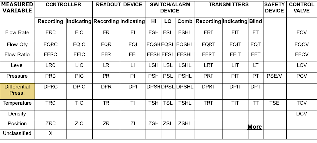
Letter is used to classify the instrument by it's function and number is used to identify the loop/interlock. Identification letters on the ISA symbols indicate:
  • The variable being measured (e.g. flow, pressure, temperature).
  • The device’s function (e.g., transmitter, switch, valve, sensor, indicator).
  • Some modifiers (e.g., high, low, multifunction).
In the instrument tag number in above figure the initial letter indicates the measured variable. The second letter indicates a modifier, readout, or device function. The third letter usually indicates either a device function or a modifier.

In that cases where the instrument is considered to be identified by it's location/area then the instrument tag number format will be as bellow:


Connected line/link and device symbol used in control loop:


Different types of symbol are used to describe the connection/link between instrument, device, controller etc.

Following line symbol are generally used for representing a complete control loop:

Symbol of control and measuring device used in process control:

Valve and Actuator


Measuring device


Instrument symbol and Identification


Measuring Instrument Symbol:


Final Element Symbol:


Related Device Symbol:


Instrument Identification Letter:


Monday, October 28, 2013

Function symbols and their uses:


Shape like circles, squares, diamonds, hexagons, and lines used to represent the hardware and software instruments and functions as follows:


  • Discrete Devices and Functions, represents discrete hardware instruments and functions that are implemented in non-microprocessor-based systems similar to single-case transmitters, controllers, indicators etc.
  • Shared Devices and Functions, represents shared and distributed software analog instruments and functions that are implemented in microprocessor-based systems similar to distributed control or programmable logic control systems.


  • Shared On–Off Devices and Functions, represents shared and distributed on–off software instruments and functions that are implemented in microprocessor-based control systems similar or equal to a distributed control or programmable logic control systems.


  • Computer Devices and Functions, represents shared and distributed on–off software instruments and functions that are implemented in a computer-based control system


Pages - Menu