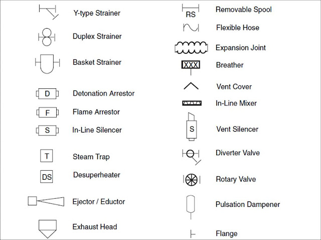
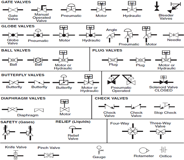
Line numbering or designation for each major line, especially header is very important to trace flow continuation for a multipage project drawing. There is several standard for such numbering system.
A line can be identified by its number, fluid to be handled, location in plant, line size, MOC etc. These parameters are the basic elements of line identity. The schematic representation of the parameters is as shown below:
Detail Description:
Line Number: Line number is a unique number assigned to every line. Every line must have a different line number i.e. the number should not be repeated for various lines.Depending on the type of fluid the lines can be further numbered. For example lines for process fluids can have numbering in one range, say, 1 to 100, utility lines can have numbering falling in another range, say, 101 to 200 and so on.
Fluid to be carried: Process lines are meant for handling various fluids. The fluids handled can be classified as Process fluids (which further includes the raw materials, the intermediate streams and the final product ) Utilities (which includes cooling water, chilled water, steam, thermic fluids, soft water, DM water etc.). For nomenclature, each of these lines are given specific codes depending on the fluid handled
CWS may indicate cooling water supply, CWR may indicate cooling water return, DMS may indicate DM water supply and so on.
Location or Area: This parameter is included in the nomenclature so as to indicate the origin of any stream in various locations of the plant. The various sections of plants are Raw material storage, processing, Intermediate Product Storage, Final product storage, Water treatment section, utility section, waste treatment section etc.
Material of Construction: Commercial pipes are available with various materials of constructions. Most commonly used materials are CS, AISI 304, AISI 316, Copper, PVC etc.
In the nomenclature MOC can be written as it is like CS for Carbon steel, AISI 304, AISI316 etc. for various grades of Stainless Steel.
Second way can be giving code for various MOC. For example Code 1 can denote CS, Code 2 can denote AISI 304 and so on.
Line size: Although the selection of line is a job of piping engineer, the line sizing can be done by Process or Piping engineer. Commercial pipes are available either as NB (Nominal Bore ) based or OD (Outside Diameter) based depending on the material of construction.
The standard sizes on NB basis are 25, 50, 80,100,150,200 etc. The corresponding sizes on OD basis are 33.4, 60.3, 88.9, 114.3, 168.3, 219.1 etc. The same are mentioned in the nomenclature.
Phase: Materials that are handled in Process plants exist in different phases. In general the flow can classified as single phase flow, two phase flow and three phase flow. Single phase flow indicates flow of solid, liquid, gases or vapors. Two phase flow indicates combination of any two of these
solid + liquid, solid + gases, liquid + vapors etc.
Three phase flow indicated combination of any three of these.
The inclusion of this parameter in the nomenclature may be optional, but the inclusion proves to be very helpful especially when the process involves several phase flows through various lines in the plant.
The details of phase can be given by complete name of the phase like solid, liquid etc.
Letters such as S, L, G and V can be used to denote respectively solids, liquids, gas and vapors.
Insulation: Process equipment and pipes are insulated either to prevent heat loss to the surroundings or to prevent heat gain from the surroundings. Accordingly there are two types of insulations – hot and cold. Depending on the temperature inside the pipe and that of the surroundings, the nature of insulation differs.
The terms “H” and “C” can thus be used to indicate the type of insulation. The inclusion of this parameter in the nomenclature is essential because it indicates the nature of fluid in the pipe which is mainly required for personnel safety in the plant.
Other: At times it becomes necessary to provide additional details in the nomenclature. These include jacketing of pipe, pipe tracing, welding type, and special lines like IBR etc. The additional detail can be indicated as it is in the nomenclature.e
A typical line number / designation should be as follows:
6044-25-L-SW4-40S-IH
6044: Serial No/Sequence
25: Nominal diameter of the line
L: Service Code
SW4: Welding Type
40S: Material Spec
IH: Insulation Type
For numbering purpose many organizations have their own format of numbering which is prepared using standard rules for equipment and line numbering.
Every organization has their own master sheet or drawing which is prepared for the purpose of standard reference and it must include all the standard symbol, notation and format required for future drawing.
Introduction to P&ID


