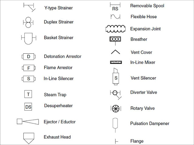
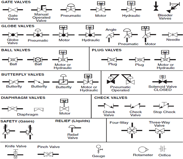
Click here for Piping and Instrumentation Diagram main article
The flow sheet or flow diagram are often used in context of engineering and design application. Although this terminology is not most accurate to describe P&IDs, it’s sufficient to describe the overall family of a process based diagram to which P&IDs belong.
We can divide the process diagram in three type or step:
BFD : The Block Flow Diagram
PFD : The Process Flow Diagram
P&ID : The Process and Instrumentation Diagram
BFD : The Block Flow Diagram
PFD : The Process Flow Diagram
P&ID : The Process and Instrumentation Diagram
BLOCK FLOW DIAGRAM
The beauty of a BFD is its ability to outline the complete process on little more than a single sheet. The diagram usually resemble an organized chart, containing mainly text enclosed by boxes, interconnecting lines, the process commodities they transport and flow arrows to indicate flow directions.
INFORMATION PROVIDED BY A BFD
A good BFD typically contains the following:
- Individual pieces of equipment or equipment package that are denoted by a single symbol, typically a rectangle.
- Clear label illustrating function
- Lines linking equipment or process to show flow direction.
- The order of process flow arranged and if possible with a gravity bias.
- Whenever more than one line leaves a process then the processed commodity in each line should be clearly marked
TYPICAL BFD
Information provided by a PFD
A typical PFD shows the following items:
The Piping and Instrumentation Diagram (P&ID), based on the Process Flow Diagram (PFD), represents the technical realization of a process by means of graphical symbols for equipment and piping together with graphical symbols for process measurement and control functions.
A P&ID carries a wealth of information that span engineering disciplines to define a process. The representation and designation of all the equipment, instrumentation and piping should comply with the requirements of Standard. Auxiliary systems may be represented by rectangular boxes with reference to the separate diagrams
For processing facilities, it is a pictorial representation of:
Ø Key piping and instrument details
Ø Control and shutdown schemes
Ø Safety and regulatory requirements and
Ø Basic start up and operational information
INFORMATION PROVIDED BY P&ID:
PROCESS FLOW DIAGRAM
Process flow diagram carry more information than the block flow diagram. They show more detail about major equipment & sub system and the flow. PFD include information of the pressure and temperature of the feed and product line to and from all major equipment. Also indicate the main header and points of all control. It’s consider as the precursor of P&IDsInformation provided by a PFD
A typical PFD shows the following items:
- Process piping
- Process flow direction
- Major bypass and recirculation lines.
- Major equipment represented by simplified symbols.
- Control and process critical valves
- System ratings and operational values.
- Composition of fluids
- Connection between systems.
PROCESS AND INSTRUMENTATION DIAGRAM
The Piping and Instrumentation Diagram (P&ID), based on the Process Flow Diagram (PFD), represents the technical realization of a process by means of graphical symbols for equipment and piping together with graphical symbols for process measurement and control functions.
A P&ID carries a wealth of information that span engineering disciplines to define a process. The representation and designation of all the equipment, instrumentation and piping should comply with the requirements of Standard. Auxiliary systems may be represented by rectangular boxes with reference to the separate diagrams
For processing facilities, it is a pictorial representation of:
Ø Key piping and instrument details
Ø Control and shutdown schemes
Ø Safety and regulatory requirements and
Ø Basic start up and operational information
INFORMATION PROVIDED BY P&ID:
- Permanent start-up and flush lines.
- Flow directions and Interconnections references.
- Control inputs and outputs, interlocks and Computer control system input.
- Interfaces for class changes.
- Identification of components and subsystems delivered by others.
- Instrumentation and designations.
- Mechanical equipment with names and numbers.
- All valves and their identifications.
- Process piping, sizes and identification
- Miscellaneous - vents, drains, special fittings, sampling lines,reducers, increasers and swagers.
TYPICAL P&ID


